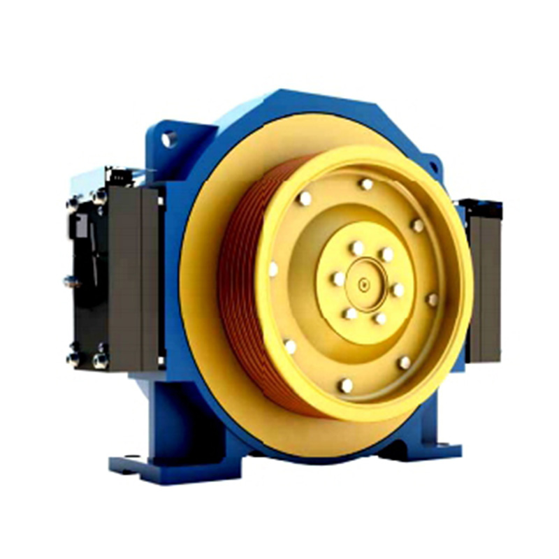
Peiriant Tynnu Di-ger Synchronous Magnet Parhaol THY-TM-K300
| Foltedd | 380V |
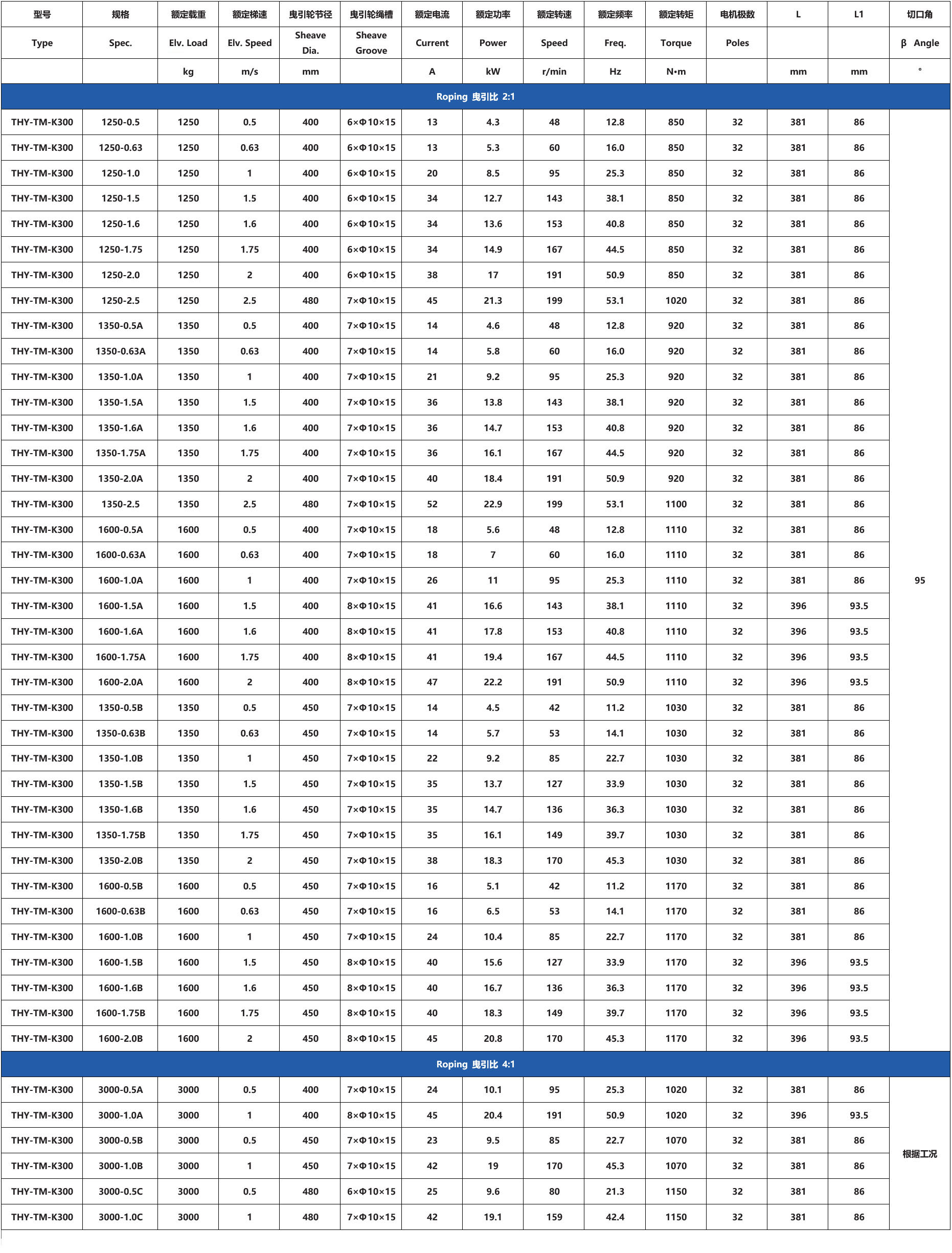
| Rhaffau | 2:1/4:1 |
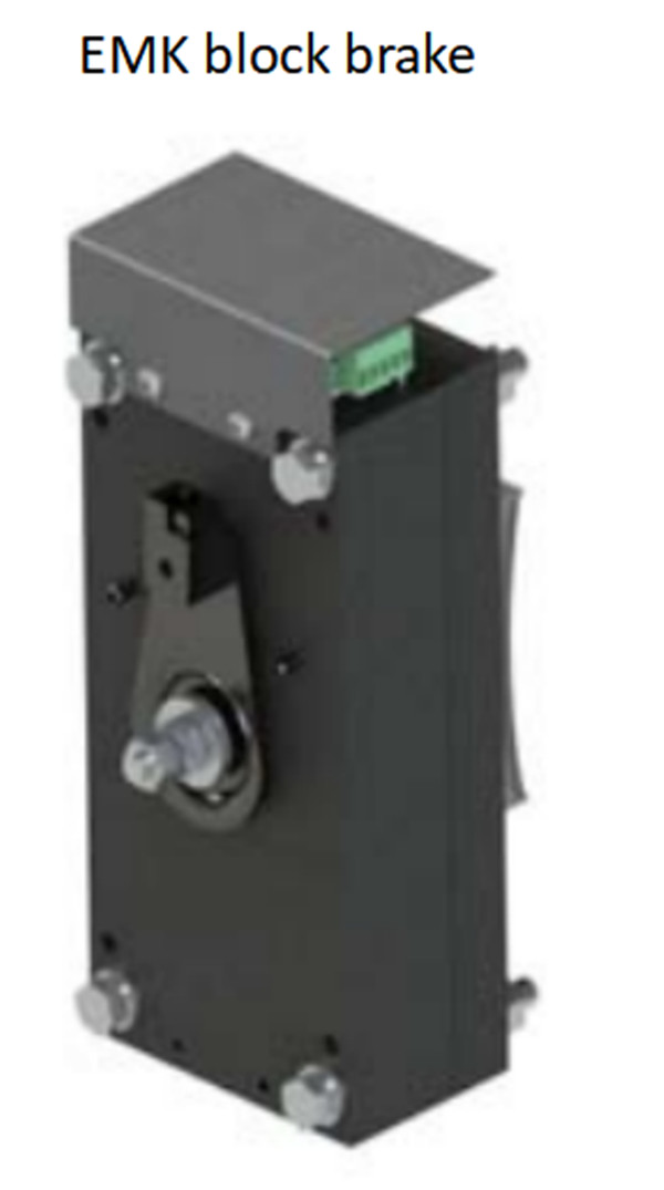
| Brêc | DC110V 2×1.6A |
| Pwysau | 520kg |
| Llwyth Statig Uchafswm | 6000kg |
1. Cyflenwi Cyflym
2. Dim ond y dechrau yw'r trafodiad, nid yw'r gwasanaeth byth yn dod i ben.
3. Math: Peiriant Tynnu THY-TM-K300
4. Gallwn ddarparu peiriannau tyniant cydamserol ac asynchronous o TORINDRIVE, MONADRIVE, MONTANARI, FAXI, SYLG a brandiau eraill.
5. Ymddiriedaeth yw hapusrwydd! Ni fyddaf byth yn methu eich ymddiriedaeth!
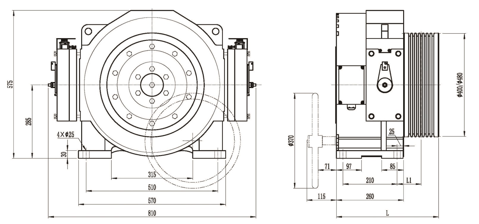
Mae dyluniad a chynhyrchiad peiriant tyniant lifft cydamserol magnet parhaol THY-TM-K300 yn cydymffurfio â "GB7588-2003-Cod Diogelwch ar gyfer Gweithgynhyrchu a Gosod Liftiau", "EN81-1: 1998-Rheolau Diogelwch ar gyfer Adeiladu a Gosod Liftiau", "GB/ Y rheoliadau perthnasol yn T24478-2009-Peiriant Tyniant Liftiau. Mae dyluniad oes dwyn y peiriant tyniant wedi bodloni'r gofynion gweithredu. Ar ôl cyfnod o weithredu (1 flwyddyn neu yn ôl yr angen), mae angen ychwanegu saim, ac nid oes angen ychwanegu na disodli saim ar gyfer berynnau wedi'u selio. I ailgyflenwi, dilynwch y gofynion chwistrellu fel a ganlyn: Chwistrellwch Mobil Grease XHP222 (gradd 2 NLGI) ar gyfer y prif beiriant gyda dyddiad cynhyrchu cyn 2018, a Shell Gadus S3 (gradd 2 V220C) ar gyfer y prif beiriant gyda dyddiad cynhyrchu ar ôl 2018. Mae'n addas ar gyfer lifft gydag ystafell beiriannau a lifft heb ystafell beiriannau. Y gymhareb tyniant yw 2:1 a 4:1, y llwyth graddedig yw 1250KG~1600KG, y cyflymder graddedig yw 0.5~2.5m/s, a gall diamedr y siwt tyniad fod yn 400mm, 450mm a 480mm. Addas ar gyfer amgylchedd gwaith dan do.
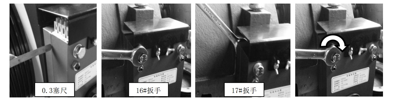
• Addaswch fwlch y brêc (y pellter rhwng y plât statig a'r plât symudol), mae bwlch y brêc yn llai na 0.1mm pan fydd wedi'i ymgysylltu, ac mae tua 0.25~0.4mm pan gaiff ei ryddhau.
• Defnyddiwch fesurydd teimlad 0.3 i wirio bwlch aer cornel y brêc: pan fydd y bwlch aer yn llai na 0.3mm, llaciwch y bollt mowntio yn y gornel hon yn wrthglocwedd, yna trowch y bollt gwag yn glocwedd ar ongl fach, ac yna tynhau'r bollt mowntio.
• Defnyddiwch fesurydd teimlad 0.35mm i wirio'r bwlch aer onglog: pan fydd y bwlch aer yn fwy na 0.35mm, llaciwch y bollt mowntio cornel yn wrthglocwedd, yna trowch y bollt gwag yn wrthglocwedd ar ongl fach, ac yna tynhau'r bollt mowntio.
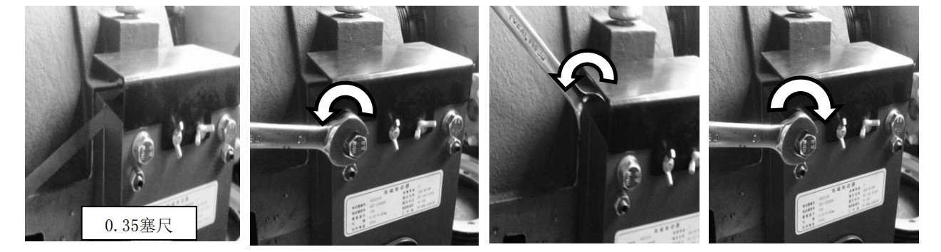
• Addaswch y bwlch rhwng pob cornel o'r brêc i sicrhau y gall y mesurydd teimlad 0.3mm basio, ac na all y mesurydd teimlad 0.35mm basio.
• Pan fydd y brêc wedi'i ddefnyddio, defnyddiwch fesurydd teimlad 0.08mm i wirio cliriad yr olwyn rhwng olwyn y brêc a'r pad brêc. Pan fydd y cliriad yn llai na 0.08mm, ailadroddwch y dull addasu cliriad y brêc, a mireinio i sicrhau bod cliriad yr olwyn yn ≥0.08mm.
• Tynnwch orchudd uchaf y brêc ac addaswch y bloc addasu switsh micro fel pan fydd y brêc yn cael ei agor/cau, y gellir agor/cau'r switsh micro yn ddibynadwy, a bod y gorchudd yn cael ei ailosod ar ôl ei addasu.
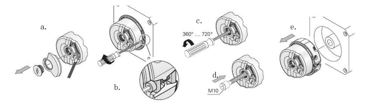
a. Defnyddiwch allwedd Allen 3mm i dynnu gorchudd cefn gwrth-lwch yr amgodiwr.
b. Llaciwch sgriw ehangu cylch allanol yr amgodiwr gydag allwedd Allen 2mm.
c. Llaciwch y sgriw M5 (2~4 tro) ar gyfer tynhau'r amgodiwr gydag allwedd Allen 4mm.
d. Defnyddiwch allwedd Allen 8mm i sgriwio'r sgriw M10 i mewn i wthio'r amgodwr allan.
e. Daliwch yr amgodiwr gyda'ch llaw a'i dynnu'n ysgafn a'i osod mewn lle diogel.
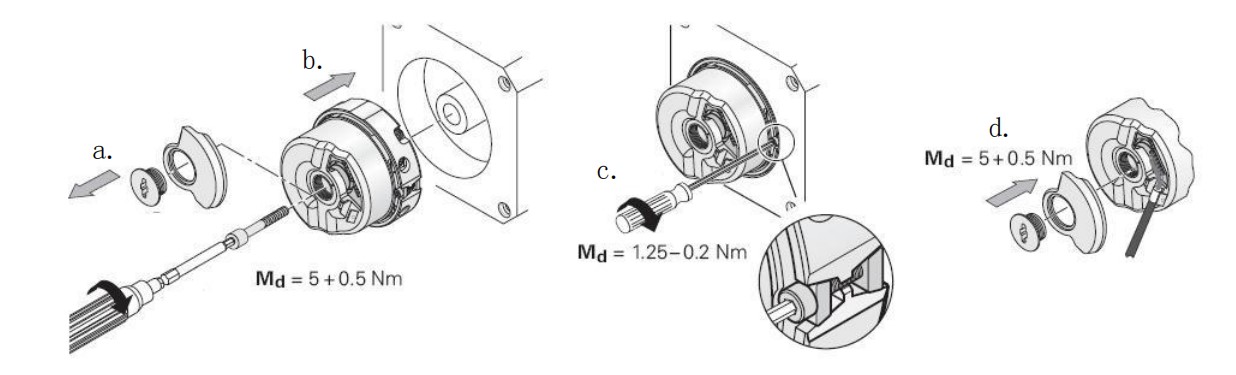
a. Defnyddiwch allwedd Allen 3mm i dynnu gorchudd cefn gwrth-lwch yr amgodiwr.
b. Tynhau sgriw mowntio M5 yr amgodiwr (grym tynhau 5+0.5Nm) gydag allwedd Allen 4mm.
c. Defnyddiwch allwedd Allen 2mm i dynhau sgriw ehangu cylch allanol yr amgodiwr (grym cloi 1.25-0.2Nm).
d. Defnyddiwch allwedd Allen 3mm i dynhau gorchudd cefn gwrth-lwch yr amgodwr (grym cloi 5+0.5Nm).